Jaw Style Coupling Assortment Approach
The variety process for determining the right jaw coupling size and elastomer needs using the charts proven over the following pages. There are 3 parts for being selected, two hubs and one particular elastomer. When the shaft size from the driver and driven in the application are in the identical diameter, the hubs picked are going to be exactly the same. When shaft diameters differ, hubs chosen will differ accordingly.
Data essential just before a coupling can be selected:
HP (or KW) and RPM or Torque of driver
Shaft sizes of driver and driven tools and corresponding keyways
Application description
Environmental ailments (i.e. severe temperature, corrosive circumstances, space limitations)
Steps In Selecting A Jaw Coupling
Step one: Ascertain the Nominal Torque of the application by utilizing the next formula:
Nominal Torque = in-lb = (HP x 63025)/RPM
Nm = (KW x 9550)/RPM
Phase 2: Using the Application Service Things Chart 1 select the services aspect which very best corresponds for your application.
Stage 3: Calculate the Style Torque of one’s application 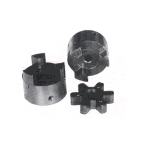 by multiplying the Nominal Torque calculated in Step 1 through the Application Services Factor established in Phase 2.
Layout Torque = Nominal Torque x Application Service Component
Phase 4: Utilizing the Spider Performance Data Chart 2, choose the elastomer material which finest corresponds to your application.
Stage five: Working with the Jaw Nominal Rated Torque Chart three , find the suitable elastomer materials column to the elastomer picked in Step four.
Scan down this column for the initially entry where the Torque Worth during the ideal column is higher than or equal towards the Design and style Torque calculated in Stage 3.
When this value is located, refer to the corresponding coupling dimension in the first column from the Jaw Nominal Rated Torque Chart 3 .
Refer for the optimum RPM worth for this elastomer torque capability to ensure the application demands are met. When the requirement will not be happy at this point, one more style of coupling might be necessary for the application. Please talk to Lovejoy engineering for help.
Phase six: Examine the application driver/driven shaft sizes to the optimum bore size accessible to the coupling selected. If coupling bore size isn’t substantial adequate for the shaft diameter, choose the subsequent greatest coupling that could accommodate the driver/driven shaft diameters.
Phase 7: Employing the UPC variety variety table , obtain the suitable Bore and Keyway sizes needed and find the variety.